Allsen Gate Valve
Gate Valve
Designed for on/off service, these valves feature a wedge that creates an unobstructed passageway when fully open, minimizing turbulence and pressure drop.
Available in various designs, including bolted bonnet and pressure seal, with solid or flexible wedge options based on size.
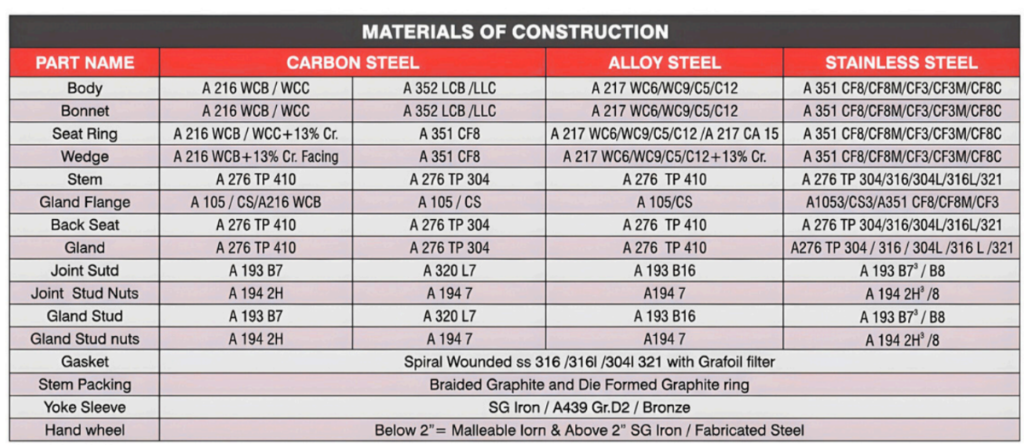
1. BODY:
Bodies and bonnets are high-quality cast and afterwards precisely machined, directing the attention to prevent stress concentration. The bodies of gate valves consist of a straight-through port that guarantees minimal turbulence and resistance to flow. In both designs, bolted bonnet and pressure seal, the bodies consist of guide slots to accommodate the wedge during the opening or closing of the valve.
2. BONNET:
Bonnets are made either of one piece only—the yoke then being an integral part of it—or of two pieces, depending on the size of the valve. This ensures the perfect alignment with the body, which leads to an accurate opening and closing.
3. BACKSEAT:
All ALLSEN gate and globe valves have a backseat threaded in the bonnet or, for the pressure seal valves, welded to the bonnet. In the pressure seal, the hard facing is Stellite 6 or equivalent.
4. BODY & BONNET GASKETS:
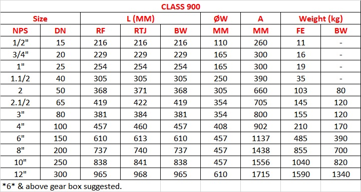
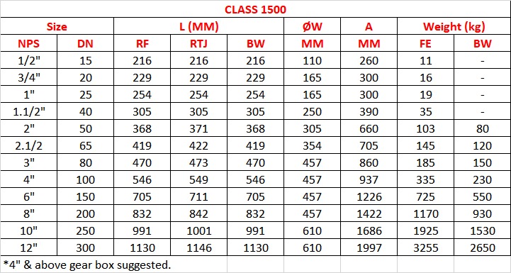
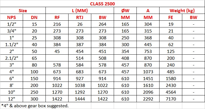
The design of the body-bonnet/gaskets varies depending on the class of the valve. Class 150 gate valves consist of a square joint for 2″ and an oval one for all other sizes. Depending on the valve service, it can be supplied with a flat-face gasket with graphite or PTFE. Class 300 and 600 valves consist of a circular, spiral-wound gasket. Class 900 and above gate valves consist of a ring-type joint. In pressure seal
The sealing is achieved through a gasket that takes advantage of the internal pressure of the line. The material most commonly used is high-purity graphite, being located between the body and the body retainer ring.
5. FLEXIBLE WEDGE:
All ALLSEN gate valves 2″ and above feature a flexible wedge unless otherwise specified by the customer. The flexible wedge shifts along the body of the valve during opening and closing, being held in position by a guide slot that minimizes the friction between the body seat and the wedge. This design is specially suited to compensate for slight thermal deformations produced by the pipe or the valve itself, safeguarding a better sealing between body and wedge seats.
SPECIAL FEATURES
Design and Manufacturing:
API 600/ISO 10434 (2″ ≤ 24″), BS 1414/ASME B 16.34 (For NPS ≥ 24) &
API 602/ISO 15761 (For NPS < 2)
Inspection and Testing:
API 598, BSEN 12266 Part – 1 & 2 MSS – SP – 61
End Flange Dimensions:
ASME B 16.5 (For NPS ≤ 24″), ASME B 16.47 Series
A & B (For NPS ≥ 24), MSS SP – 44 (For ≥ 24)
BW End Dimension: ASME B 16.25
Face-to-Face & End-to-End Dimension: ASME B16.10, BS2080
Gasket Design: ASME 16.20
Wedge Design: Solid Wedge for NPS < 2″ & Flexible for 2″ ≥ NPS
TOLERANCE
Face to Face: ± 2.0mm for NPS ≤ 10″ & ± 3.0 mm for NPS > 10″
DESIGN FEATURES
Gear Operation-applied force exceeds 350 N
Limit Switch Arrangement
Electrical & Pneumatic Arrangement
Lantern ring arrangement for Vacuum service
IBR Certified
NACE MR 0175 & MR 0103
Position indicator
Locking Arrangement
Extended Stem