Overview
A technical guide to identifying, understanding, and preventing the five most critical failure modes that compromise valve performance across industrial operations.
Key Takeaways
- Valve failure is rarely sudden — it is the cumulative result of identifiable and preventable mechanical, chemical, and operational stresses acting over time.
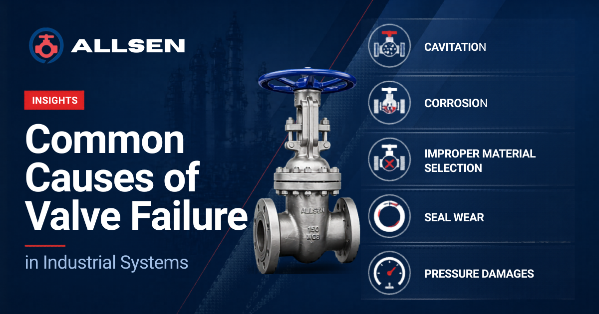
- The five primary failure causes: Cavitation, Corrosion, Improper Material Selection, Seal Wear, and Pressure Damages; Account for the majority of unplanned valve outages in industrial systems.
- Each failure mechanism demands a distinct engineering response: from fluid dynamic analysis for cavitation to alloy specification for corrosion resistance.
- Proactive maintenance strategies, including scheduled inspections, torque testing, and fluid compatibility audits, can extend valve service life by years and drastically reduce unplanned downtime.
- Matching the valve type, material grade, and seal specification to the actual process conditions is the single most effective measure in preventing premature valve failure.
Valves are the control points of every industrial process — managing flow, pressure, and fluid direction across systems that range from municipal water networks to high-pressure petrochemical reactors. When a valve fails, the consequences extend far beyond the valve itself: unplanned shutdowns, process contamination, safety incidents, and costly emergency replacements cascade through operations that depend on uninterrupted flow control.
Yet valve failure is rarely a sudden event. In most cases, it is the end result of a slow, identifiable process — a deteriorating seal, an incompatible material quietly corroding, or a cavitating fluid steadily eroding internal surfaces. Understanding these root causes is not merely an academic exercise; it is a practical engineering discipline that directly impacts plant reliability, maintenance budgets, and safety compliance.
This article examines the five most prevalent causes of valve failure in industrial systems — cavitation, corrosion, improper material selection, seal wear, and pressure damage — and provides actionable maintenance guidance to help engineers and plant managers keep their valve assets performing reliably throughout their intended service life.
Hydrodynamic Damage
Cavitation: The Silent Erosion of Valve Internals
Cavitation is one of the most destructive and most frequently misunderstood mechanisms of valve failure in industrial systems. It occurs when the local static pressure within the flowing fluid drops below the fluid’s vapor pressure, causing the liquid to flash into vapor bubbles. As these bubbles travel downstream into regions of higher pressure, they collapse violently, releasing intense shock waves and microjets that can generate localized pressures exceeding 1 GPa at the impact surface.
In valves, this phenomenon most commonly occurs at the point of flow restriction, typically between the valve disc or ball and the seat where high-velocity flow creates a localized low-pressure zone. Control valves, pressure-reducing valves, and throttling ball or butterfly valves operating at high differential pressures are particularly vulnerable. The result is a characteristic pitting and cratering of metallic surfaces, often described as resembling an orange peel or golf ball texture. Over time, cavitation erosion removes material from trim components, seats, and valve bodies, progressively degrading shutoff performance and increasing leakage.
Beyond material damage, cavitation produces intense noise that often is described as a sound similar to gravel passing through the pipeline and severe vibration that can loosen bolted connections and damage adjacent instrumentation and pipework. Recognizing these auditory and vibrational signatures early is critical to intervention before catastrophic damage occurs.
Prevention & Mitigation
Cavitation control begins at the design stage. Anti-cavitation trim, featuring tortuous-path or multi-stage pressure drop designs is the most effective engineering solution which distributes the pressure reduction across multiple stages so that local pressure never falls below vapor pressure. Material upgrades to hardened alloys (Stellite, 17-4PH stainless, or hard-faced trim) extend resistance to cavitation erosion in existing installations. Operating valves at higher backpressure or installing downstream flow restrictors are also effective system-level countermeasures.
Maintenance Tip: Schedule periodic internal inspection of control valves operating at high differential pressures (ΔP > 50% of upstream pressure). Early-stage cavitation pitting caught during planned maintenance costs a fraction of an emergency trim replacement or body repair.
Chemical Degradation
Corrosion: Chemical Attack on Valve Materials
In almost every industry, corrosion is the most common danger to valve longevity. It is the chemical or electrochemical deterioration of valve materials brought on by an interaction with the environment, the process fluid, or both. Unlike cavitation, which mechanically erodes surfaces, corrosion targets the molecular structure of metals, gradually decreasing wall thickness, raising surface roughness, and finally compromising the valve’s structural and sealing integrity.
In industrial valve systems, corrosion appears in several distinct forms. The most predictable and controllable type of corrosion is uniform corrosion, which is easily prevented by choosing the right materials and applying protective coatings. Far more insidious are pitting corrosion, which creates deep, localized penetrations that can perforate a valve body while leaving the surrounding material relatively intact, and crevice corrosion, which attacks areas of stagnant fluid within tight geometries such as threaded connections, under gaskets, or within valve packing glands. Pitting corrosion, which produces deep, localized penetrations that can pierce a valve body while leaving the surrounding material largely intact, and crevice corrosion, which targets areas of stagnant fluid within tight geometries like threaded connections, under gaskets, or within valve packing glands, are far more subtle.
Perhaps the most disastrous type is stress corrosion cracking (SCC), which happens when a vulnerable material is subjected to both tensile stress and a corrosive environment at the same time. The most frequent situations in the oil, gas, and chemical processing industries are austenitic stainless steels in chloride-containing fluids and carbon steels in hydrogen sulfide (H2S) environments (sulfide stress cracking, according to NACE MR0175/ISO 15156).
When different metals come into electrical contact with one another in an electrolytic fluid, the less noble metal corrodes more quickly due to galvanic corrosion. This is a frequent issue in multi-material valve assemblies or at pipe-valve interfaces where material consistency has not been specified.
Corrosion Control Strategies
A multi-layered strategy is needed for effective corrosion management: choosing corrosion-resistant alloys suitable for the particular fluid chemistry (duplex stainless, super duplex, Hastelloy C-276, or Inconel for extremely aggressive media); applying internal linings or coatings (PTFE, epoxy, rubber lining); installing cathodic protection on buried or submerged valves; and keeping process chemistry controls to reduce the concentration of corrosive species. Every maintenance program should incorporate routine corrosion monitoring using ultrasonic thickness measurement and visual inspection procedures.
Engineering Specification
Improper Material Selection: An Upstream Failure
The primary cause of many valve failures that manifest as corrosion, erosion, or mechanical failure in operation is a mistake made long before the valve was installed: the incorrect material was specified for the application. An upstream failure is one that occurs during the engineering or procurement stage and pays for itself over the course of the valve’s operational life.
The consequences of material mismatch are extensive. Whereas a 316L stainless steel or coated ductile iron substitute would have lasted for decades, a carbon steel body valve placed in a brackish or mildly acidic water system may corrode violently in a matter of months. A typical NBR elastomeric seat designed for a service fluid containing aromatic hydrocarbons will quickly swell, deteriorate, and lose its ability to seal. Without taking into account the thermal barrier, a valve body rated for standard service temperatures placed next to a steam header may experience creep, distortion, or fastener relaxation, which could result in flange leakage.
The entire complexity of the service environment must be taken into account when choosing a material: fluid chemistry, including pH, dissolved ions, and entrained solids; temperature extremes in all operating modes, including start-up, shutdown, and upset conditions; pressure class requirements; and cyclic or dynamic loading that impacts fatigue life. Industry standards such as ASME B16.34 (pressure-temperature ratings for valves), NACE MR0175 (sour service material requirements), and API 6A (wellhead equipment) provide essential frameworks for material specification in their respective domains, but they are reference points — not substitutes for — a thorough process-specific analysis.
Avoiding Material Mismatch
The best defense against material mismatch is to involve valve manufacturers early in the engineering process and provide them with comprehensive fluid data sheets, P&ID context, and worst-case operating conditions. For any critical or high-consequence service, a materials compatibility matrix review that compares all valve-wetted materials to the process chemistry ought to be a required step in the valve specification and requisition process.
Maintenance Tip: Always double-check the process conditions against the original specification when replacing valves. Over the course of a plant’s life, process fluids, temperatures, and pressures frequently fluctuate; a valve that was properly specified at commissioning may no longer be suitable for the current service conditions.
Mechanical Degradation
Seal Wear: The Progressive Loss of Shutoff Integrity
The parts of any valve assembly that require the most upkeep are the seals and packing. They serve as the interface between the external environment and the internal fluid pathway of the valve, and they are constantly under mechanical, thermal, and chemical stresses that eventually lead to degradation. The most frequent reason for external leakage (fugitive emissions) and poor shutoff performance in industrial valves is seal wear.
The seat seal, which offers shutoff between the closure element (disc, ball, gate) and the valve body, and the stem packing, which stops leaks along the valve stem to atmosphere, are the two separate components of valve sealing systems. Both are susceptible to wear and are essential to the integrity of the valve.
Seat seal wear is primarily driven by repeated operation cycles, especially when subjected to high differential pressure or in the presence of abrasive particles in the fluid stream. Soft-seated valves — using PTFE, EPDM, or PEEK seat materials — offer excellent shutoff performance but are more susceptible to wear and deformation than metal-seated designs. In applications requiring high cycle frequency (thousands of operations per year in automated systems), seat wear can become a dominant maintenance cost driver, making metal-to-metal or hard-faced seat designs the more economically sound long-term choice.
Stem packing wear and fugitive emissions are subject to increasingly rigorous regulatory requirements. Standards including ISO 15848-1, TA Luft (German VDI 2440), and EPA Method 21 set permissible leakage rates for valve stem emissions, particularly for volatile organic compounds (VOCs) and toxic fluids. Live-loaded or spring-energized packing systems, which maintain constant gland load as packing material consolidates or creeps, have become the industry standard for emission-critical applications.
Seal Maintenance Best Practices
Packing adjustment or replacement intervals should be defined based on fluid service, cycle frequency, and regulatory requirements — not deferred until visible leakage occurs. Many facilities implement a leak detection and repair (LDAR) program, using portable VOC analyzers to identify packing emissions before they reach reportable thresholds. Seat seals in high-cycle automated valves benefit from periodic in-situ leak testing against ANSI/FCI 70-2 acceptance criteria to confirm continued sealing performance.
Structural Integrity
Pressure Damage: Overpressure, Water Hammer, and Fatigue
Pressure-related damage encompasses a spectrum of failure mechanisms — from the sudden catastrophic rupture of a valve body subjected to gross overpressure, to the insidious accumulation of fatigue damage from thousands of pressure fluctuation cycles. In each case, the valve experiences mechanical stress in excess of what its design and materials can reliably sustain.
Overpressure events occur when system pressure transiently or persistently exceeds the valve’s maximum allowable operating pressure (MAOP), as defined by its pressure class rating per ASME B16.34 or the equivalent standard. Common causes include pressure relief valve malfunction, blocked outlets, thermal expansion in trapped fluid volumes, and uncontrolled pump surge. Even brief overpressure events can plastically deform valve bodies, distort seats, or crack bonnet flanges, leaving a valve that passes visual inspection but has been permanently compromised in structural integrity.
Water hammer — the hydraulic shock wave generated by rapid valve closure in a liquid-filled system — is a particularly damaging and frequently underestimated pressure damage mechanism. When a fast-acting valve (such as a solenoid or pneumatic actuated ball valve) closes in milliseconds, the momentum of the flowing liquid column is arrested abruptly, converting kinetic energy into a high-amplitude pressure wave that propagates through the pipework. Peak water hammer pressures can reach two to ten times the normal operating pressure, subjecting valves, flanges, and pipe supports to forces far beyond their design basis.
Pressure cycling fatigue occurs in systems with frequent or significant pressure fluctuations — compressor discharge lines, pulsating pump systems, and pressure let-down stations. The repeated stress cycles accumulate damage in the valve body, bolting, and welded connections, potentially leading to fatigue crack initiation and propagation at stress concentration points such as nozzle junctions or geometric transitions.
Pressure Damage Prevention
Water hammer mitigation strategies include specifying actuators with adjustable close speed, installing surge suppressors or cushioned check valves, and performing transient flow analysis during system design to identify vulnerable closure scenarios. Pressure relief and safety valve systems must be periodically tested and recertified to ensure they lift at the correct set pressure. For fatigue-sensitive applications, valves should be specified to the appropriate fatigue life class per design codes, and pressure cycle logs maintained to track accumulated duty.
Proactive Reliability
Consolidated Maintenance Tips for Valve Longevity
A structured preventive maintenance program, tailored to the specific failure risks of each valve in service, is the most cost-effective tool available to plant reliability engineers. The following best practices address the five failure modes discussed above:
🔍 Regular Inspection Intervals
Schedule valve internals inspection based on service severity — annually for moderate duty, semi-annually for high-cycle or aggressive fluid services. Use borescopes for non-intrusive internal surveys where accessible.
📋 Fluid Compatibility Audits
Review process fluid chemistry annually and cross-reference against valve wetted material specifications. Flag any changes in pH, concentration, or temperature that may have moved outside the original design envelope.
⚙️ Actuator & Torque Testing
Verify actuator breakaway and running torques against valve manufacturer requirements at each major turnaround. Excessive torque demand is an early indicator of seat damage, packing over-compression, or stem corrosion.
⚙️ Actuator & Torque Testing
Verify actuator breakaway and running torques against valve manufacturer requirements at each major turnaround. Excessive torque demand is an early indicator of seat damage, packing over-compression, or stem corrosion.
💧 Leak Detection (LDAR)
Implement a formal LDAR program using portable analyzers to detect stem packing and flange gasket emissions. Address findings before they escalate to reportable releases or require emergency intervention.
📁 Valve Asset Register
Maintain a complete asset register recording each valve’s service conditions, material specifications, maintenance history, and inspection results. Data-driven maintenance decisions consistently outperform time-based schedules.
Conclusion
Valve failure in industrial systems is rarely inevitable — it is, in most cases, predictable and preventable. The five failure modes examined in this article — cavitation, corrosion, improper material selection, seal wear, and pressure damage — each follow recognizable patterns with established engineering countermeasures.
The foundation of valve reliability is sound engineering from the outset: specifying the correct valve type, material grade, and seal system for the actual process conditions, and building a maintenance program that identifies deterioration before it becomes failure. As industrial systems grow more complex and regulatory requirements more stringent, the cost of reactive valve maintenance — in downtime, safety risk, and environmental liability — continues to rise. Investment in proactive valve reliability is not a maintenance cost; it is operational insurance with a measurable return.
For valve manufacturers and end users alike, understanding failure mechanisms is the first step toward designing systems that endure.
FAQs
Several in-service indicators point to cavitation without requiring valve disassembly. Characteristic noise — a crackling or gravel-like sound from within the valve or downstream pipework — is the most recognizable symptom. Elevated vibration at the valve body and adjacent supports, visible pitting or discoloration on downstream piping, and unexplained increases in seat leakage or flow coefficient are also strong indicators. Acoustic emission monitoring and ultrasonic testing can be applied non-intrusively to confirm cavitation activity in critical valves.
The most common causes of stem packing failure are over-compression (which extrudes or cracks the packing material), under-compression (which allows leakage as the packing consolidates), thermal cycling that causes packing to shrink and lose sealing force, and chemical incompatibility between the packing material and the process fluid. Prevention involves selecting packing materials verified against fluid chemistry, applying live-loading systems that automatically compensate for packing relaxation, and following manufacturer-specified gland follower torque values during installation rather than tightening to feel.
Corrosion is the mechanism of material degradation; improper material selection is the root cause that makes a valve susceptible to that mechanism — or to others such as erosion, swelling, or embrittlement. A valve made of 316 stainless steel in a high-chloride service will fail by stress corrosion cracking not because corrosion is unavoidable, but because 316 SS was the wrong material choice for that environment. Addressing corrosion symptoms in service (coatings, inhibitors) is a second-order fix — the primary solution is to specify the correct material from the outset.
Yes. Pressure transient monitoring using high-frequency data loggers installed at strategic points in the piping system can capture water hammer events and quantify their magnitude. Repeated impacts are recorded in the data before visible valve or pipe damage occurs, enabling system modifications — such as actuator speed adjustment, surge suppressor installation, or operational procedure changes — to be implemented proactively. Visual inspection for deformed bonnet bolts, distorted gasket faces, or cracked pipe supports can also indicate historical water hammer exposure.
There is no single universal interval — maintenance frequency should be risk-based and informed by the valve’s service severity, criticality to operations, failure history, and condition monitoring data. As a general framework: safety-critical valves (PSVs, ESDVs) should be tested at the intervals mandated by applicable standards (e.g., API 527 for pressure relief valves; ISA 84 for safety instrumented systems). Process control valves in moderate service are commonly scheduled for overhaul every two to four years, while high-cycle or aggressive fluid service valves may require annual attention. A valve asset register with condition-based monitoring data is the most reliable basis for interval setting.
Protect Your Valve Assets
If you are reviewing valve specifications for a new project or assessing reliability risks in an existing system, our engineering team is available to help you evaluate material compatibility, failure risk, and maintenance strategy — tailored to your specific process conditions.